|
Setting the Clipping Plane
You may have noticed your objects further away mysteriously disappearing. The computer uses clipping planes to save memory. There is a cubic area where models exist, outside of that region they disappear.
In any of the modeling windows, choose View->Camera Attribute Editor...
Under Camera Attributes:
If you need to, adjust Far Clip Plane to a number higher than 10000.
Adding CVs to the End of a Curve
In the Modeling Module:
Select the curve you would like to add points to. This adds to the end of the curve.
Use the Curves->Add Points Tool.
Hit Enter key to finish
If you want to add points to the beginning of a curve you will need to use Curves->Reverse Direction.
Adding Edit Points and CVs to the Middle of a Curve
In the Modeling Module, using the object type button:
Hold the mouse over the curve, use the right mouse key to bring up the curve menu:
Choose Curve Point
Drag the curve point along the curve until it is in the desired position. Use shift to add more than one point.
Use Curves->Insert Knot to add a CV and an edit point on the point location
Curve Points can be used to detach curves with Curves->Detach.
Absolute Vs. Relative Transformations
Have you noticed when you transform an object it moves exactly as input. This is an absolute transformation. For example: Rotate an object 90 degrees, then rotate it 10 degrees. The object will be rotated 10 degrees. An object rotated with a relative transformation would have added 90 + 10 and rotated 100 degrees. Relative mode adds or multiplies the new transformation to the existing transformation. The software defaults to absolute transformations. Occasionally, you will find a need for relative, especially when you are working with exact measurements.

Switch the selection button to Relative transformation on the status line, way over on the top right side of the screen. (Sometimes this is hidden if your screen is small, click on the show/hide buttons to expand hidden sections.) Select a move, scale or rotate manipulator. When you enter a value in the box the object or component will transform using a relative transformation.
Rebuild Curves
This tool can help redistribute points more evenly across a curve.
Select the curve, choose Ctrl and a to bring up the Attribute Editor
Check how many spans your curve has.
Use Curves->Rebuild->
Number of spans: chosse a number related to the number of spans your object has.

Rebuild NURBS Surfaces
This tool can clean up unnecessary points or isoparms
Use Surfaces->Rebuild->
Rebuild Type: Uniform
Parameter Range 0 to 1
Number of Spans U 4, Try adjusting this value.
Number of Spans V 4, Try adjusting this value.
Degree U 3 Cubic, Try 1 Linear if you want a faceted object.
Degree V 3 Cubic, Try 1 Linear if you want a faceted object.
Output Geometry NURBS, Try Poly if you want to convert NURBS to Poly.
Click Rebuild
Mesh Reduce
Mesh->Reduce->
Change Percentage 70
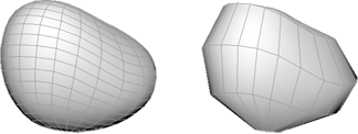
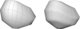
Mesh Retopologize
Mesh->Retopologize
You will need to reassign UV coordinates.
Birail
Draw two curves to be used as paths (or tracks).
Draw one generation curve that will move along the paths. Use point snap or curve snap to line up the generation curves to the paths.
Select the generation curve first, and use the shift key to the two paths.
Select Surfaces->Birail 1 Tool
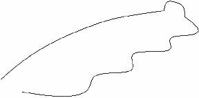
Two paths and a round generation curve.
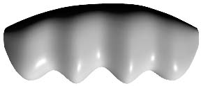
The result.
Birail will let you to use more than one generation curve so that the shape of the surface can vary across the paths. Birail can also create a new tangent surface between existing surfaces by Selecting isoparms.
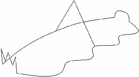
Two paths and three generation curves.
Square is another tool which is similar to Birail in that it can create tangent surfaces and requires the curves to line up.
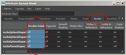
Attribute Spread Sheet for Render and Tessellation
Use this window to change attributes on multiple objects, for example, change all the objects in you scene to single sided at once.
Choose Windows->General Editors->Attribute Spread Sheet
Choose the Render Tab
Click in the field under Double Sided where it reads off
Click in the Double Sided Box to highlight the entire column
Type 1 for on, 0 equals off.
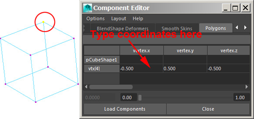
Component Editor for Poly Point Positions
Use this window to change attributes for components, for example, change the xyz position of multiple vertices.
Choose Windows->General Editors->Component Editor
Choose the Polygons tab
Type in an XYZ value for one of your vertices.
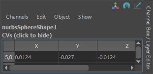
Component Coordinates for NURBS and Polygons
Use the Channel Box
Select the CVs on NURBS or the vertices on Polygons
Click on the node in the Channel Box labeled CVs (click to show)
You can edit the position of the CVs here.

|