|
Switch over to the Modeling section, choose from upper left, status line.

Make sure the select by object type button is selected in the status line near the top for all examples. 
Draw a Mesh
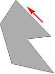
Use Mesh Tools->Create Polygon Tool to draw a polygon
Draw counter clockwise in most cases. This insures the shape is not inside-out.
Hit Enter when you are done creating the shape
Bevel Plus a NURBS curve to make a poly beveled object
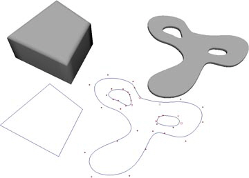
Choose Create->Curve Tools->CV Curve Tool->
Click on Curve Degree 3 Cubic for rounded curves, use 1 Linear for straight curves.
Draw the outer curve counter clockwise.
Hit Enter button on the keyboard when you are finished.
Choose Curves->Open/Close Curvesl-> to close to close
Select Shape: Ignore
(Or draw the last point on top of the first with point snap.)
Add holes if you like, draw them clockwise.
Select outer curve first, then the inner curves if you want to bevel with holes.
Choose Surfaces->Bevel Plus->
Select Convex Out
Extrude distance: .5
Create cap: At start and At end
Under the Output Options tab
Output geometry: Polygons
Along Extrusion, Samples: 1
Adobe Illustrator curves can also be brought in to use with Bevel or other tools. (Save as an old Illustrator format such as 8.0)
Curve to Flat Polygon Mesh with Bevel Plus
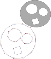
Start with a NURBS curve. Create->Curve Tools->CV Curve Tool Make sure the curve is closed, or the first point is on top of the last point (use v point snap). You can also add holes with this procedure. This creates something similar to planar surface, the geometry is cleaner.
Select the curve(s), outer curve first
Choose Surfaces->Bevel Plus ->
Under Bevel tab:
Create bevel: Check At start, uncheck At end
Bevel width: 0
Bevel depth: 0
Extrude distance: 0
Create cap: Check At start, uncheck At end
Under Output Options tab:
Along Extrusion: Samples: 1
Along curve: Samples: For Linear curve degree, input 1, for Cubic curve degree, input 3 or more
Click Bevel
Select the model and run Mesh->Cleanup...
Select Lamina faces (faces sharing all edges)
This will get rid of all double surfaces.
Select the model and run Edit Mesh->Merge->
Make sure the Tolerance is very small
Extrude (poly)
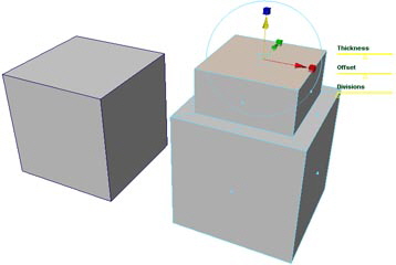
Choose select by component type  and make sure the faces button and make sure the faces button  is pushed in; this will allow you to select faces. Select the top face by clicking on the little square in the middle of the face. is pushed in; this will allow you to select faces. Select the top face by clicking on the little square in the middle of the face.
Select Edit Mesh->Extrude
Click the red box at the end of the red arrow of the extrude manipulator to change to scale mode. Select the box at the center of the manipulator and scale down the face a little.
Hit "g" to run Extrude again)
Click on the blue arrow and drag straight up
You may also use rotate to add extrusions.
Later try animating extrude for Game of Thrones title sequence effect. Any tool can be animated though construction history.
Extrude to make a Hollow Body or Offset Surface for thickness
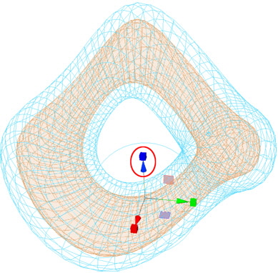
If you would would like a hollow body follow these instructions.
View wireframe mode, hit 4
Right mouse to select all the faces
Select Edit Mesh->Extrude.
Select Keep Faces Together (This option is on the mini menu.)
Move the blue (z axis) extrude arrow to the desired thickness.
Soft Selection
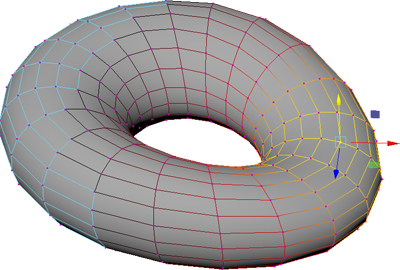
Double click the Move tool on the left to bring up the Tool Settings. 
Open the Soft Selection Section
Enable Soft Select:
Change to Select by Component Type 
Select Poly Vertices

Select a vertex and move it.
Play with the Falloff radius options.
Turn off Soft Select when you are done. (Soft Select is also turned on for Rotate and Scale.)
Switch back to select by object type near the top. 
Delete Face
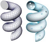
Use the Right Mouse button over your polygon to bring up the mini menu to select Face
Hit Delete
(This is a poly primitive Helix)
Delete Edge/Vertex
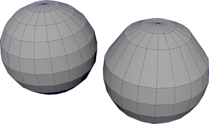
This is a great way to clear up extra polygons
(A vertex usually cannot be deleted individually, first delete the edge.)
Select the Edges
Right mouse over an edge, select Edge from the mini menu, double click the edge to select the entire ring. (You may need to select and edge and double click the one next to it.)
Use Edit Mesh->Delete Edge/Vertex
Multi-Cut
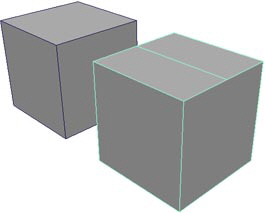
Select Mesh Tools->Multi-Cut Tool
Hold down Shift, click on an edge and drag down until the point snaps to 50% then release.
Now click on the opposing edge and drag down until the point snaps to 50% then release.
Select another tool such as the Select Tool to stop the Multi-Cut. 
This added 2 vertices, an edge and a face to a cube.
Fill Hole
Use Mesh->Fill Hole to fill in if there is one hole on your model. (Select by object type near the top.  ) )
(This tool works best if there is 1 hole to fill or maybe 2.)
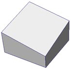
Insert Edge Loop
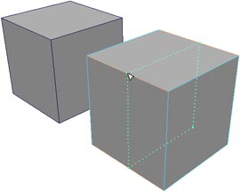
Select Mesh Tools->Insert Edge Loop Tool
Click and drag to add new edges (polygons and vertices)
Append to Polygon
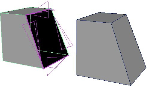
Select Mesh Tools->Append to Polygon Tool
Select an edge to start
Look at the arrows, select the next edge following the arrows
Keep selecting edges until you are finished
If needed, use the Selection tool to end 
Bevel
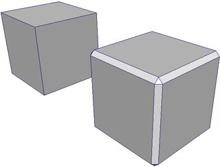
Select Edit Mesh->Bevel->
This will add a bevel to an entire object or selected edges
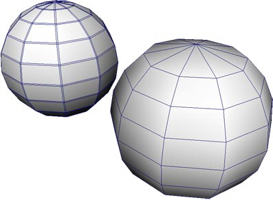
Merge
Use Edit-Mesh->Merge-> (Open the dialogue window.) (Open the dialogue window.)
Set Threshold to .0001 (This depends on your model)
This will cleanup redundant vertices
Make sure you threshold tolerance is not too large, otherwise you will lose faces.
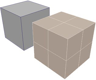
Add Divisions
Select Edit Mesh->Add Divisions->
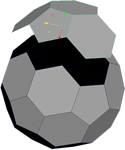
Extract a Polygon into a separate shape
Right mouse over the shape, select Face, select the faces you want to separate
Choose Edit Mesh->Extract
Combine Polygons
Select all the polygon shapes you would like to combine.
Choose Mesh->Combine
Separate Polygons
Select a poly object
Choose Mesh->Separate
Use a Boolean Operation to add more divisions
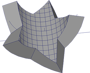

Create a Star
Choose Create Polygon Primitives->Disc->
Select Sides: 10
Select Subdivision Mode: Pie (less verticies)
Select Subdivisions: 1
Right mouse over the disc
Select Vertex
Select every other vertex
Use Scale to scale in the points.
Remove the edges on the face of the star:
Select the Edges
Right mouse over an edge, select Edge from the mini menu.
Use Edit->Delete
Use Edit Mesh->Extrude to extrude the star
Create the Cube with Divisions
Create->Polygon Primitives->Cube-> with extra divisions on the top surface. with extra divisions on the top surface.
Width divisions: 10
Depth divisions: 10
In the persp view menu, select Shading->Wireframe on Shaded
Hit 5 for shaded too
Intersect the cube into the extruded poly shape, there should be overlaps.
Select the extruded star shape, then select the cube.
Select Mesh->Booleans->Intersection
Use Edit->Delete by Type->History
Use Deform->Nonlinear->Bend
Rotate the bend deformer 90 degrees in Z to match the intended bend
Use the Channel Editor to modify the Curvature of the Bend
Use Edit->Delete by Type->History again to delete the deformer in order to bring the shape into Unity.
Display Poly Counts
Select Display->Heads Up Display->Poly Count
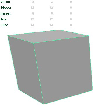
Any NURBS Tool can be used to create Polygons, Loft
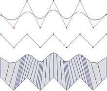
Switch over to the Modeling section, choose from upper left, status line.
Draw a couple NURBS curves, Create->Curve Tools->CV Curve Tool
Select Surfaces->Loft->
Choose Polygons
Choose Quads
Choose Tessellation method: General
Change U type to: Per span # of iso params
Change V type to: Per span # of iso params
Input Number U: 3 (If this is too jaggy, increase)
Input Number V: 1
Hit Apply
Chord Height
If you are texture mapping a loft shape, you may want to try this.
Draw a couple NURBS curves, Create->Curve Tools->CV Curve Tool
Select Surfaces->Loft->
Choose Polygons
Choose Quads
Choose Tessellation method: General
Change U type to: Per span # of iso params
Change V type to: Per span # of iso params
Input Number U: 1 (Leave lower when using chord height ratio)
Input Number V: 1
Select Use chord height
Hit Apply
This will add more polygons.

NURBS Planar Surface to Make Polygons

Draw one or more curves, place one inside of the other.
Use Curves->CV Curve Tool->
Select the outer curve first, the the rest
Select Surfaces->Planar->
Choose Polygons
Choose Quads
Choose Tessellation method: General
Change U type to: Per span # of iso params
Change V type to: Per span # of iso params
Input Number U: 1 (If this is too jaggy, increase)
Input Number V: 1 ""
Uncheck Use chord height (default not selected)
Hit Apply
You may clean up the extra edges and vertices, see image above
Right mouse over poly, select Edge from the mini menu, select all inner edges.
Use Edit Mesh->Delete Edge/Vertex
Right mouse over poly, select Vertex, make sure all the extra vertices are deleted.
Sphere from a Cube for better Texture Mapping
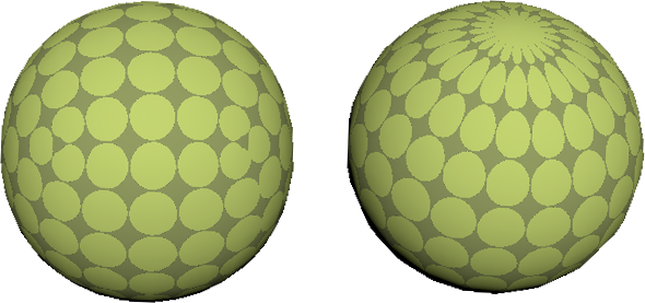
Cube-Sphere versus a Poly Sphere
Select Create->Polygon Primitives->Cube->
Select Edit->Reset Settings
Select Each face separately
Image Texture Map
Select the cube.
Use the right mouse key over cube to bring up the marking menu, select Assign Favorite Material->Standard Surface.
Under the Attribute Editor, on the right side of the screen  (Or Ctrl a) (Or Ctrl a)
Find the new Standard Surface Shader tab.
Click the Map Button across from Base Color 
Select the File icon 
Change Filter Type to Off (less blurry, default Quadratic)
Choose an image 
It is best to keep your images in the scenes directory for Maya.
And keep a copy of your image in the Assets directory for Unity.
Under Arnold
Change Filter Type to closest (less blurry, default smart_bicubic)
Hit 6 (shader display) to view the texture shaded on the model.
Smooth the Cube into a spheroid
Select the Cube
Run Mesh->Smooth, 2-3 times
You may repeat the texture in the hypershade window. 
Select the Textures tab
Double click the texture
In the Attribute Editor, switch to the place2dTexture tab
Change Repeat UV to a higher value.

|