|
Download these files.
PC: Right Mouse Extract All...

UV Poly mapping Dice
Create a polygon cube Create->Polygon Primitive->Cube
Select the Cube
Use the right mouse key over the cube to bring up the marking menu, select Assign Favorite Material->Lambert or Phong for Unity, Standard Surface for Arnold.
In the Attribute Editor, on the right side of the screen  (Or Ctrl a) (Or Ctrl a)
Find the new Shader tab.
Click the Map Button across from Color 
Select the File icon 
Change Filter Type to Off (less blurry)
Choose Image Name locate the dice_texture.tif image 
It is best to keep your images in the scenes directory for Maya.
Or keep images in the Assets directory for Unity.
Under Arnold change Filter Type to closest (default smart_bicubic, less blurry for render.)
Hit 6 (shader display) to view the texture shaded on the model.
File->Save your scene into your Unity Assets folder
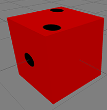
Hit 6, you will see you the texture is not mapping correctly. The dot on the dice are stretched and 2 faces on the side appeared as empty.
To fix this problem, you could select individual faces and assign individual texture, but that means you need 6 materials for one object, which is very inconvenient.
Here, we try to modify the UV mapping to solve the problem, and have the object use only one material.
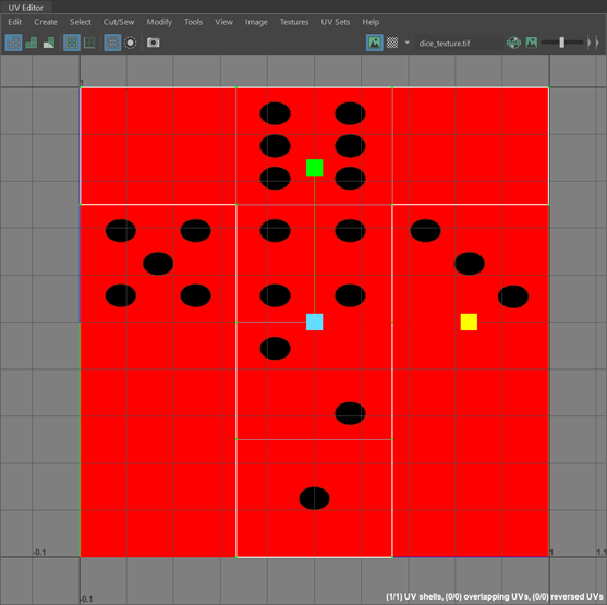
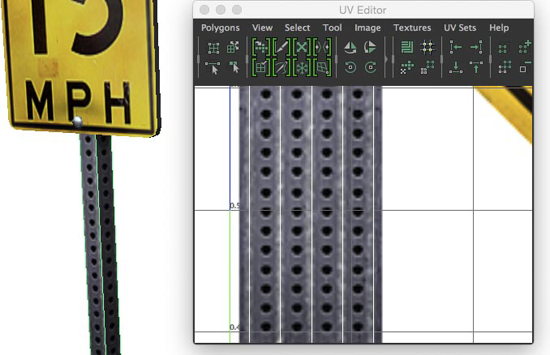
Make sure the cube is selected, and open UV->UV Editor.
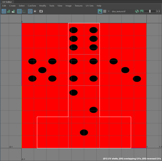
Dolly out
Right mouse key menu select UV
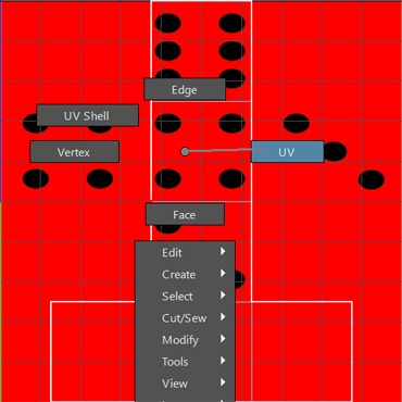
Marquee select all the UVs.
Note: all transform tools you use to move, rotate and scale objects apply to UV->UV Editor.
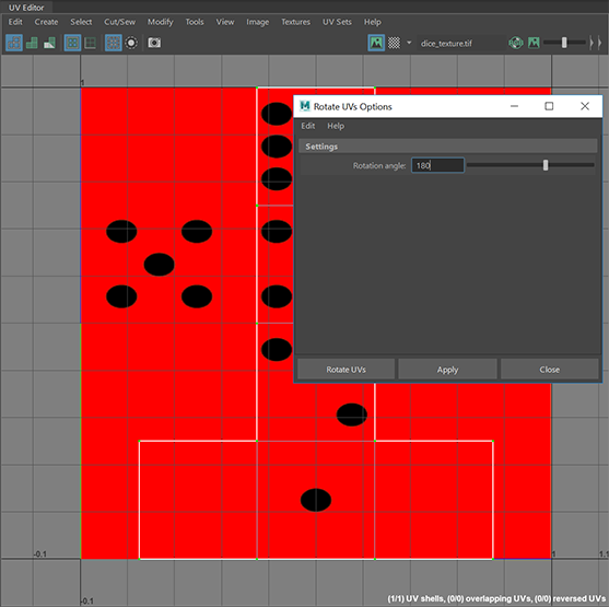
Or, click on Modify->Rotate->
 (in the UV Editor) (in the UV Editor)
Enter 180 for the Rotation angle and click Apply.
Use the modeling scale manipulator to scale the UV in X and move to match up with the texture as shown below. 
Now, the dots on the cube are no longer stretched, but we still have two faces missing.
Right click select Face.
Use shift to select the top left face and right face.
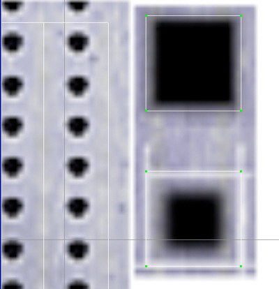
In the UV->UV Editor menu bar select Cut/Sew->Cut

These two faces are now separate UV components.

Right click select Face, use shift to select both faces.
Select the Move Manipilator on the left 
Change the pivot center by holding down the d key and then v
Drag the Pivot to the lower left corner of the first face.
Use x to grid-snap the faces vertically down to the new location.
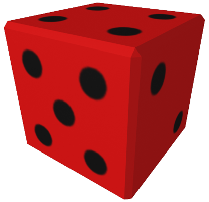
Now, you have a dice perfectly textured with a single material!
Normal Maps
Select the Lambert shader.
Click the Map Button across from Bump Mapping 
Select the File icon 
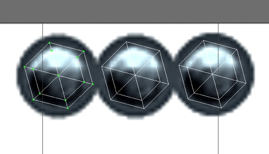
New tabs called bump2D and file will appear in the Attribute Editor.
Bump Depth will change the apparent height of the bump, you may use negative values.
Change Use As: to Tangent Space Normals (default Bump)
Go to file tab in the Attribute Editor.
To the right of the Image Name click the folder icon. 
Choose a normal map image.
MEL Scale UVs Precisely for Texture Repeats
Create->Polygon Primitives->Sphere
Create a Lambert material with a texture map.
Make sure the sphere is selected, and open UV->UV Editor.
Right mouse over the unwrapped shape
Select UV
Marquee select all the UVs
Zoom out the UV Editor window (Use the mouse scroll wheel etc)
Use Tools->Scale (This selects the Scale manipulator)
Scale the shape to the size of about 4 textures
Choose Edit->Undo (in the main menu)

Open the Script Editor, by pressing the button in the lower right side of the screen. 
(Or Windows->General Editors->Script Editor)
Scroll down the top section in order to see the most recent commands.
Find the MEL command code that looks like this: polyEditUV -pu 0.5 -pv 0.5 -su 4.996906 -sv 4.996906 ;
Highlight the code
Edit->Copy the code
Edit->Paste the code in the lower section.
Edit the code, change the last 2 numbers, these are the repeats, the first 2 numbers are the pivot center.
polyEditUV -pu 0.5 -pv 0.5 -su 5 -sv 5 ;
Make sure the UVs are selected
Highlight the revised code in the lower section.
Run Command->Execute from the Script Editor menu

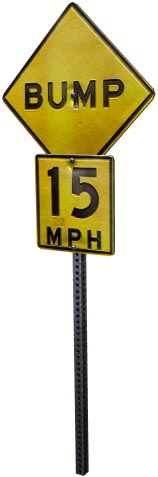
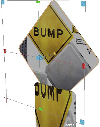
UV Poly mapping Bump Sign
Open sign_bump_undone.ma
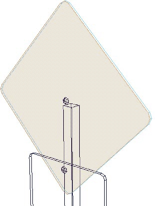
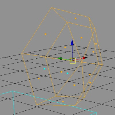
Select all the frontal faces of the diamond shape include the bottom face hidden in the rectangle. You can press 4 to view wireframe select that face.
In the Modeling section

Select UV->Planar->

Choose Fit Projection to: Bounding box
Choose Project from: Z axis
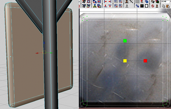
After creating the planar mapping, you will see a manipulator (the bounding box), which allows you to move the UVs around the texture image.
Press 6 to show the texture to see the interactive changes when you play with the manipulator.
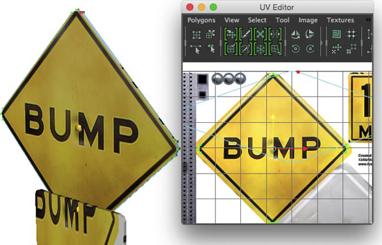
Use the handle and scale box to fit the bump sign to the diamond.
You can also move the manipulator in the UV->UV Editor.
Play around with the manipulator until the texture fit perfectly as below.
Select all the back face of the diamond including the faces of the border.
Create a Planar Mapping again, and fit the manipulator to the back metal texture as below (outer edge to the outer edge of the metal).
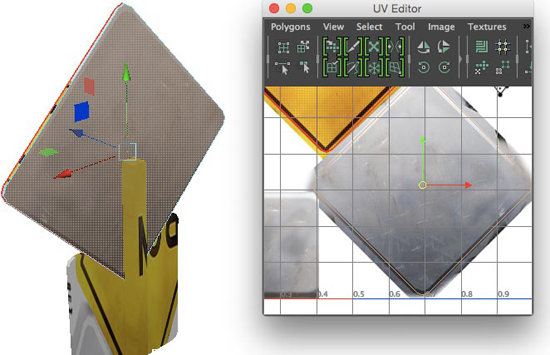
Now the edge UVs are overlapping, we have to unfold it.
Select only the back faces of the diamond (excluding the border).
In UV->UV Editor, Choose Select->Convert Selection-> to UVs.
Now, you have the UVs selected on the faces you had selected before.
Scale the UVs down to the inner edge of the border as below.
Repeat the process to the rectangle.
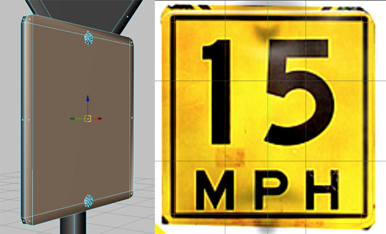
The back side of the rectangle
In Object mode, select the bolt on the diamond sign.
In UV->UV Editor, choose Select->Convert Selection->to UVs.
For the Bolt, you don't have to create a planar mapping, move and scale it to the bolt texture. Complete all 3 bolts.
Select the faces of the pole except the top and bottom faces.
In the Modeling section, in the menu bar, select UV->Cylindrical.
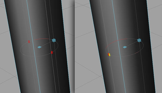
You will see the manipulator is different to the planar one. It is in a cylinder shape.
Zoom to the middle part of the manipulator.
Drag the scale handle to make a complete circle of cylindrical mapping.
Scale and move the manipulator in the UV->UV Editor to fit the UVs to the pole.
Select and create planar mapping to the top and bottom face of the pole separately.
Note: you should project from Y axis this time.
UV Poly mapping Car
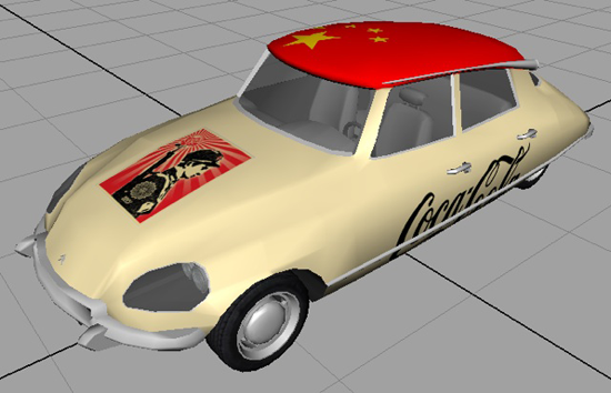
Select the car body.
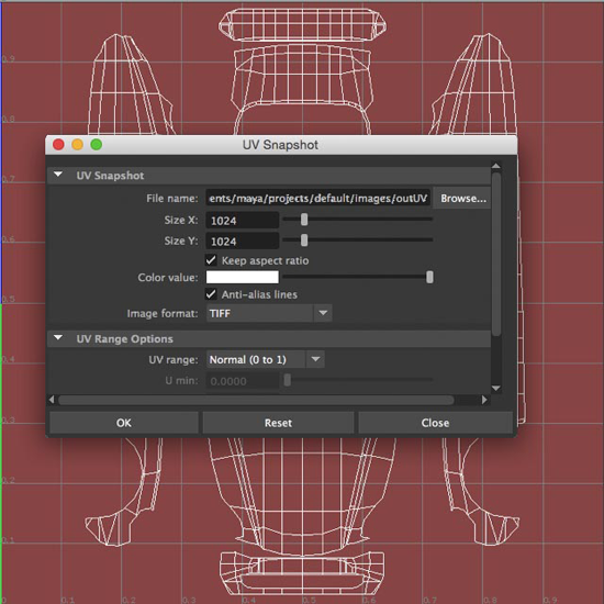
Open UV->UV Editor.
From the menu bar select Image->UV Snapshot
Click Browse to locate the destination of the UV snapshot image.
In Photoshop:
Open you snapshot tiff in Photoshop.
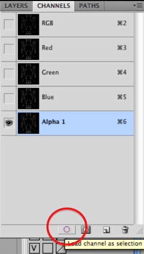
Go to Channels, select Alpha 1, and click the icon Load channel as selection.
Go to layer, add a new layer and fill it with blue.
Delete Alpha 1.
Now, for the fun part. You can drag on the wireframe to draw anywhere on the car body.
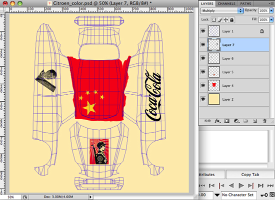
Save your texture as a psd file, name it as Citroen_color.psd
Note: you should hide the wireframe layer when you save the psd, otherwise it will appear on the car body.
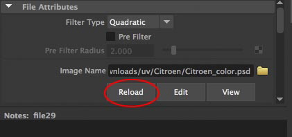
Back to Maya assign the texture to the car body material.
Every time you edit and saved the image in Photoshop, you should press the Reload under the attribute of the texture to update the image.
Note: The UV mapping corresponds to any images assigned to the material of the object. ie. color, bump or specular map share the same UV coordinates.
Unity Baked Light Map UV Setting
UV Settings for non-texture maps models: (especially if you see light map UV errors.)
Select your object
Select UV->Automatic->
Percentage space: .5

|